Hello !
I got a MM 2100-150 to fix (sometimes, it blows fuses : HT or main power).
I have checked the 6L6. According to my tube tester (Hickok), they seem OK (although I did not test them on another amp).
I measured output power and I get 2V RMS max clean (1kHz) on 8Ω (< 1W) !!!
Heat voltage is correct, anode voltages are 730VDC on Hi and 500VDC on LO, screen grid voltages : 380V (HI), 250V (LO).
I'm a tube tech not very familiar with transistors and transistor biased MM (I have a nice 2100-65 w/ 12AX7 PI I fixed a few years ago with great help from "old" pacair forum ;-) ). So, I was surprised at first not finding any AC signal on 6L6 grid 1 (pin 5), but I suppose the signal "enters" via cathode (wow !). Anyway, I have 8VDC on grid 1 instead of 22VDC as seen on schematic, maybe a problem here.
The "bias" (=voltage) found at R39 and R40 was 150mA ! I corrected it down to 25mA and 35mA
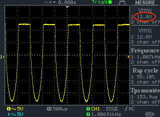
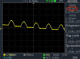
I took 2 pictures of the signal at the collectors of Q3 and Q4 (with a 1VRMS 1kHz signal at the transistors base, clean).
Here is what i get (see pictures) : one seems correct (is it ?), the other seems completely odd
I'm really not a transistor guy ... what do you think ? Do I have to replace Q3 and Q4 (and check components around : resistors, capacitors ...).
Thanks a lot for your help !


Where to start?
Check and fix the 3 low voltage power supplies first by checking the zener diodes for +22V (D12) and +/-16V (D13,14). At only 8V on the control grids, it sounds like your D12 zener may be shot. The hi V supply numbers you gave sound good. Once the lo voltages are correct, check and set the bias voltage again across R39 and 40. After all that, give the signal test another try. To get familiar with diode and transistor testing with a DMM, check out this tutorial: http://www.elexp.com/electrical_measurements_part_3.aspx Nice scope BTW. Good Luck, -mgriffin
Thanks mgriffin155 !
Thanks mgriffin155 !
I order today a few zener diodes (16V, 22V), 2 transistors and electrolytic capacitor to give this amp a new blood !
I will let you know !