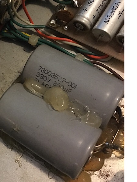
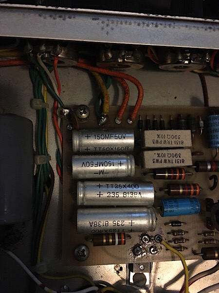
My RD100 has these 350uf 330v beasts next to the power supply, and then has 25x400 and 150mf50v next to that. I don't see these values on the schematic for the GD-2A (6L6 version, white pinwale, EV 12L). Can I find these values and if not, what are good replacement brands/values? My amp tech is great with most amps, but I want some intel in order to point him in the right direction. In other words, I'm trying to do some research rather than pay him to get up to speed on this amp.
Images:


These are not original
Hello Cmarcelli,
the two 350uF capacitors in your pictures are not original to the amplifier. They should be removed along with the wiring that connects them to the rest.
Sincerely,
Lars Verholt
Thanks for the info. They are
Thanks for the info. They are quite ugly! Do I replace them with something or just clip the wires?
No idea
Hi Cmarcelli,
removing the caps is just the first step. Whatever needs to happen after that depends on how the amp has been modified. From your pictures, we cannot decode what has been done to the amp. Are the original 2 x 100uF caps still in place? If so, are they connected? All these, and more, questions have to be answered before you can start the job. If your tech is worth paying money to at all, he (or she) should be able to figure this out easily. RD-100 amps only require 2x100uF @450V for filter caps in the high voltage section.
Sincerely,
Lars Verholt
Same caps in dog house
I did some poking around and found two things. First, there are two more of the same caps in the dog house. 350uf / 350v. Second, the ones on the interior of the chassis go to pin 6 of both tubes (A) and to ground (B). Looks like the ones in the dog house do the same thing. The schematic shows a pair of 100uf 450v caps. These values are easy to find...not sure why these 350/330 weirdo caps are even there.
What are they doing there?
Thanks for the pics under the dog house. The puzzle is much clearer now. It looks like a previous owner wanted to add extra punch to the Hi Voltage Power Supply with those 4 big caps. 2 350uF @ 330V caps connected in series would make a single 175uF @ 660V cap which is larger than the standard 100uF @ 450V cap. From the pictures, the modification work looks clean. Are they causing problems with the amp? -mgriffin
Thanks for that info. The
Thanks for that info. The caps don't seem to be causing problems and I'm not sure I could hear the difference if original spec caps were installed. Maybe I could? That said, the amp seems too "present". Is that punchy? I had thought it was the EV12L speaker making it so fast to react, but it sounds almost too quick to react through other cabs as well. Would 70uf and extra voltage handling change the tone much?
I'll admit that comparing it to a stock '74 Fender Twin isn't fair, but a Twin is closer than a Princeton PRRI. Maybe the caps are overkill? I'm thinking that an amp with a solid state pre, solid state rectifier, and EV12L isn't the best candidate for even more punch. Anyhow, the caps are at least 15 years old so I think I'll replace them. I also had the driver transistors fail, but that's probably unrelated.
More Headroom?
Whoever commissioned the Big Cap mod may have used it for a keyboard amp or something that needed more headroom. Who knows. I guess you've tried the tone controls to smooth the rough edges. Anyway, good luck on the re-cap. Going back to stock caps is fine. Have your tech visually inspect and test all the zener diodes too. Those are nice amps when all the innards are working properly. -mgriffin
Thanks for the help. The
Thanks for the help. The techs around here are fed on Fender and they look at this amp and don't know what to make of it. Your help and the knowledge on these forums helps so much. I had a tech that took a couple months to diagnose and replace some transistors. I asked about a power supply recap and he said these were fine, which they technically are. He said "leave the stock caps if they work." There's a time and place for letting the pro do his job. This amp isn't that time or place.