
New member here, seeking tech help.
Amp: HD 130
-12ax7 gain stage post preamp
-LM1458 phase inverter
-cathode driven EL34's
-mod added to bypass 12ax7 gain stage (my work)
History: Amp came to me with no drive signal at the EL34 cathodes. One driver transistor was poorly replace, so I installed a new matched pair. Now drive signal to one EL34 pair. Traced back to the LM1458 phase inverter to find one side was shorted (- rail measured low at -3v). Replacing the LM1458 fixed the failure, now the amp is working properly. Played the amp for a few hours, then went back for a final check inside the amp. Probing around, measured the cathode voltage (while be driven) on one pair, THEN when I touched the cathode on the other pair, the LM1458 failed.(coincidence?) (Maybe this somehow cause a voltage spike that returned to the LM1458 input via the feedback resistor?) Replace the LM1458 and the amp is working fine again.
I'm thinking with this extra 12ax7 gain stage, its exceeding the LM1458 max input voltage and/or max differential voltage.
I need help deteriming what is happening here as I'm green when it comes to SS and hybrid amps. (I do know to discharge o-scope probes when probing high voltage tube stages then SS stages) I need to know how this failure occured so I know its fixed for certain.
This circuit is not on any schematic I've seen. Seems like a transitional circuit, and possibly not engineered properly.
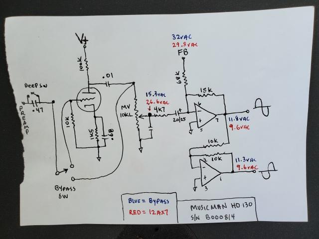
Attached is a schematic of the actual circuit in question. The voltages are taken with all controls set to max except the reverb and tremolo controls set to zero. Power amp driven to full distorted output.
Thanks for any help!
-Blake
Looks Good
I'm just a retired engineer but your work looks good. How does it sound and behave with the tube out of the circuit? There are some folks in this group that have a lot of hands on experience. MM210 and LMV. Hopefully we will hear from them soon. The amp looks like it went through half of the tube to SS Phase Inverter upgrade. BTW: It looks safe. -mgriffin
mgriffin 155, thanks for the
mgriffin 155, thanks for the reply!
With 12ax7 stage bypassed it sounds different obviously, but how?
-More headroom (due to less drive into the phase inverter),
-More bass (really it's not more, the 12ax7 Ck is .68uf)
-Better symmetry
This may sound better or worse to some depending on style of music and guitar pickups. I think I like it better for rhythm, and maybe overall but I am used to clean Fender amps.
Yes, they only wired one triode. M.M. most likely was transitioning circuits and still had the punched chassis with the 12ax7. The early circuit uses the other triode as a Cathodyne phase inverter, so I'm not sure how this compares to the SS phase inverter.
One other thing, I'm seeing a small ringing in my otherwise clean sine wave output, on the falling edge. Measured with a 100Mhz scope, driven to near full output into a non inductive load. This anomaly quickly disappears as the master volume is reduced. This anomaly is greatly excited when the tremolo intensity is advanced.
The hard part of this repair is the amp came to me dead, and this is the only MM amp I have ever had in my possession. Sooo, I don't know what they are supposed to sound like!!!
SS PI is Safer
Hi Blake, With the risk of being ripped a new one, it's been my experience that MM Amps look and sound a lot like Fenders. MMs were designed to be "Clean". I haven't heard the term Cathodyne since I was in Hi School, but yes, that is what the earlier models used for PI. Cathodynes work great until they don't and are subject to a Chernobyl effect when things go south. They also get funny when over driven. As I mentioned, you've done real good. It's great that LMV tuned in to coach you through the fine tuning stuff. -mgriffin
Thanks for the reply and
Thanks for the reply and encouragement. As I continue to expand my knowledge, having guys like you and LMV sharing knowledge is greatly appreciated. I have no proper schooling in electronics. I'm self taught so to speak, reading books that I don't understand and experimenting till I do. Through hands on repair work, I have gained understanding of text and theories that I did not grasp before. Ah ha moments, then I'll go back and re-read the subject now with the capacity to understand what it's telling me. And obviously youtube, we can almost learn everything, but I refer back to books like the RCA handbook, since this is where all the info is mostly derived from. So again, thank you to all of you who help us green horns along!
About the Chernobyl effect, I have not heard of this, I will certainly read up on it.
Oddball circuit for sure
Hi there,
interesting circuit for sure. I have heard of this sort of 'version' of the amp, or rather, I have read about it. Can't remember where but probably on this forum back in the day. This could either be the work of MM converting an original unit in this fashion, a repair shop doing it or of course an individual with electronics skills. Having this tube stage intact allows for overdriving the 12AX7 with the preamp section and then setting the master volume to the desired level. The resistors around the first driver stage of the op-amp phase splitter are stock, as are the resistors of the first 12AX7 stage. The original tube phase splitter design has the NFB signal enter at the cathode of the first 12AX7 stage. In this case the NFB signal enters at the negative input of the driver op-amp - you would get positive feedback if you moved that loop back to the original position of the tube stage, unless you reversed polarity to the output tubes. Anyway, the LM1458 phase splitter/driver setup was designed to be sensitive enough to drive the amp without the extra gain stage before it. My suggestion would be to add a suitable resistor in series with R47 (the 4.7k) and short it out when the switch is in bypass position. This way you can maintain the same overall amp sensitivity but with the option to add the extra tube stage.
Cheers,
Lars Verholt
Lars, thanks for the reply!
Lars, thanks for the reply!
Judging by the solder, components, wire used and looming of wires I believe this to be a factory job.
I am working off of 2475-130 & 2275-130 schematics. Neither are exact to this amp. The 12ax7 components are not exactly stock, this amp has a .68uf bypass cap, and an .01 coupling cap. These schems show this stage un-bypassed and a .047 coupling cap. With a .68uf Ck gain starts to rise at 156hz providing a mid boost (correct me here). Seems Marshall bright channel inspired.
Interesting idea on adjusting R47. This was the first tweak I did to the amp; I tacked in a 100k pot. I believe I had to use the complete resistance to tame the gain. Next I tried adding a volume pot in place of the 10k grid leak on the 12ax7. At this point I had lots of flexibility but no practical way to implement such control without modifying the chassis. I finally landed on keeping the 12ax7 stock with a bypass option via the disabled SPDT ground switch.
With your suggestion in mind, I think I will go back and experiment with R47 again and see if I can balance the bypass and non bypassed stages to similar amplitude.
PS
Just thought of something else - loading the plate of the 12AX7 with a 10k pot is not optimum. I bet you could get a different sound by trying out a larger value pot in this position - 100k or higher. The original design is a 1M pot. You would have to consider the coupling cap as well if you experiment.
Cheers,
Lars Verholt
Yes, I did notice that on the
Yes, I did notice that on the schematic. Wasn't sure, but felt it wasn't right since I have never seen a volume pot that low in value in a tube amp. I will try this out.
Thanks!
Blake