| Author | Message | ||
| Christophe Servais (neodyms) Username: neodyms Registered: 01-2011 |
Hi all ! I'm new on this forum i'am repairing a MusicMan 210-65 with 12AX7 phase inverter for a french musician. when he give me it's amp the fuse blow every time i switch it on. i changed the plates diodes and plates caps i also changed the two 16v zener diodes which burned a bit the PCB. Now when switch it on : OK but No sound from the input in the speakers when i switch the standby one of the 2 El34 became "Blue" and i get a big "HUM" so i think i have more than on problem but where to start ? PS : sorry for my english i'm french cordially christophe | ||
| Mike Kaus (mm210) Username: mm210 Registered: 05-2006 |
I have to think that MAYBE you should start with the filter caps under the doghouse cover and every other electrolytic cap on the board. THe hum could be from bad filter caps OR it could be a really bad tube. When you say one tube is blue, that in itself is not a problem but if it turns RED, THAT'S a problem. I would look at the caps in the power suppy and get a spare set of tubes to sub for diagnostic purposes. Also, I MIGHT look into making a current limiter( the light bulb in the hot side of the circuit) to limit the current rush and keep from eating fuse in case it starts THAT up again.. Mike. | ||
| Lars Verholt (lmv) Username: lmv Registered: 11-2009 |
Salut Christophe! In no particular order: 1. Are the DC voltages around the output tubes in the correct range? 2. Does the hum go away if you pull the 12AX7/ECC83 tube (lampe)? 3. Does the hum level vary with the master volume? -Lars Verholt www.captain-foldback.com | ||
| Steve Kennedy (admin) Username: admin Registered: 03-2002 |
I would suggest pulling the output tubes out of the amp and THEN start verifying voltages in order to prevent any possibility that you might hurt the output transformer or speakers! Steve | ||
| Christophe Servais (neodyms) Username: neodyms Registered: 01-2011 |
ok thank you all for your suggestions i will start today by checking all that point before answer your questions. @lars verholt: the um vary with the master volume. thanks a lot for your quick answer | ||
| Christophe Le Crom (vignau) Username: vignau Registered: 08-2010 |
I Christophe, I am french as well and have a pb that is discussed in help topic (210HD french export: voltage service).I did not solve my pb so far because I have not time these months. Mike and Lars gave me lot of good advices and I will have to carry on finding the pb, I will let them know when I will have found time to solve that pb. If you want, you can call me, I am in Pau we can have a talk. My phone number is 06 77 18 70 94 | ||
| Christophe Servais (neodyms) Username: neodyms Registered: 01-2011 |
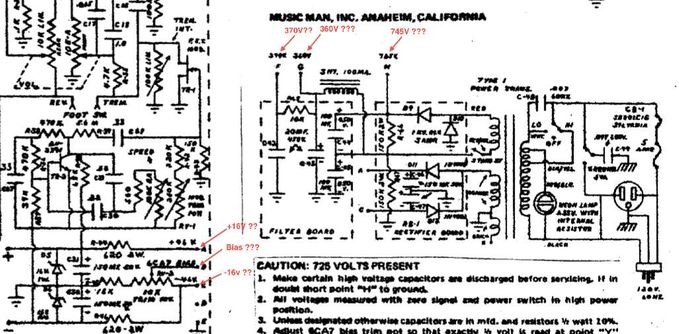
so i checked some voltages in place of +16V ; -16V I got around + 30V and -16V and i don't know which other values i have to get because i have a very dirty schematic i think to read 370v, 360v and 745v What voltage values am i suppose to get when the lamps are unplugged ?  | ||
| Mike Kaus (mm210) Username: mm210 Registered: 05-2006 |
Just seeing the voltages that you have posted, you should look at all the caps and compnents at the bias section, particularly c47. That should feed the bias circuit and it shows that you have very little control voltage at point C. The voltage will go up slightly with the tubes pulled. | ||
| Lars Verholt (lmv) Username: lmv Registered: 11-2009 |
The correct voltages are: H: 725V, G: 360V , F: 340V, A: +46V, C: -46V. What are the voltages at the big + and - points? If one or both zener diodes are shorted, you would get some strange values. Also check the 620 ohm resistors, they may have drifted. -Lars Verholt | ||
| Christophe Servais (neodyms) Username: neodyms Registered: 01-2011 |
the voltages at the big + & - are +16v & - 16v so i changed all electrolytic Caps and now get right +16v and - 16v i had a little phone dialogue with christophe Le Crom and he suggest a little things ; when the schematic was created power voltage in EU was 220v actually we are arround 230v and in a short future 240v so the two 16v zener diodes are calibrate to 1 W perhaps a quite small. Actually this Musicman Sound ! hey hey ! I am waiting for a full kit of brand new Valves Tubes. i will post next all the voltage i get and would i like to adjust a right EL 34 bias . do you know the procedure ? | ||
| Christophe Servais (neodyms) Username: neodyms Registered: 01-2011 |
ok so i changed tubes caps 16v Zener diodes etc... adjusted bias to get 0,5v on the 10ohm resistor near the cathode the amp work but the 16v power supply is quite hot! i measured voltage on the 620 ohm resistor i get 31V !! so 50 mA and 1,55 Watt to dissipate for this resistor and the zener diode witch are hot I found 1N5353 zener diode witch is 5w power dissipation |
Tue, 03/25/2014 - 09:34
#1
